Variable Capacitor Motor Control
I have been doing some
research on loop antennas, and used the internet to find out information. The
antennas are small metal loops, using cooper half inch or three quarter inch
type of tubing which can be purchased at Lowe’s, Home Depot, or other pluming
sources. They are narrow band and require soldering, the fittings and are very
high Q antennas. They usually use a capacitor which only uses the stator
plates, in series, which may be welded or soldered, but do not use the rotor
plates, because there is a loss in the moving bearing on the capacitors. They
are trying to keep the losses, to a very small amount. The antenna has a very
high voltage at the capacitors.
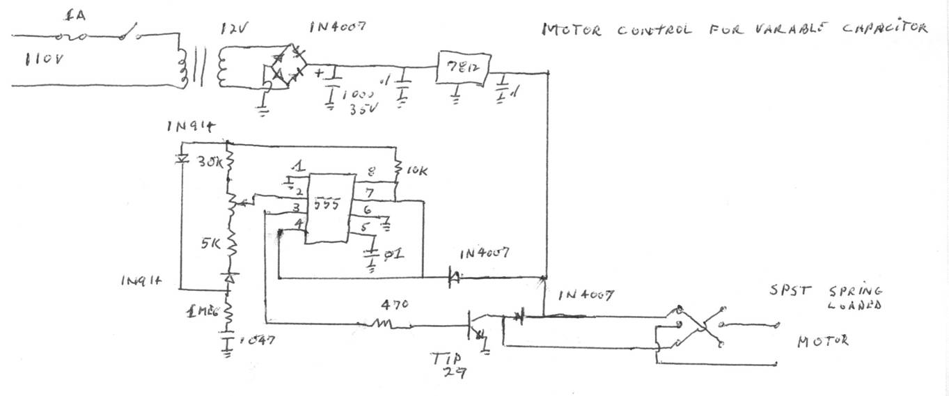
I found several circuits for building remote motor
control units. I tried several, and was not happy with how they worked. I found
the circuit below, which I built, and it worked all right. The circuit pulses
the motor and also has a variable resistor (trimmer) which you can use to
reduce the motor speed, thereby slowing down the tuning of the capacitor. I
used a 12 volt geared motor, and found that 4-5 volts gave me a slow enough
speed to rotate the capacitor which was coupled and insulated, to the gear
motor.
The circuit can be used in a
remote tuner arrangement as well.
Dave
WA2DJN